Editing symbol definitions
To understand symbol definition types and color categories, and the relationship between symbol definitions and instances, see Concept: Vectorworks symbols and Concept: Object instances, definitions, and styles.
For blue and red symbol types, editing the symbol definition affects future placement of groups or plug-in objects only, since these symbol definition types do not create symbol instances.
For black and green symbol types, changes to the symbol definition affect all existing and future instances of the symbol. The symbol definition can either be edited from the Resource Manager, or from an instance in the drawing. Editing the symbol definition from the Resource Manager displays only the symbol while editing, but editing the symbol from the drawing area allows you to edit the symbol definition within the context of the drawing. Other objects in the drawing can be visible, grayed, or hidden depending on two settings in the Display pane of the Vectorworks preferences: Show other objects while in editing modes and Gray other objects. When other objects are visible, they are also snappable, which makes it is easier to edit the symbol definition quickly and accurately in relation to those objects.
The Show other objects while in editing modes preference does not work when editing a symbol definition from a flipped symbol instance; an alert message displays when this operation is attempted.
Symbol definitions provided by Vectorworks cannot be edited in the Premium Libraries or Vectorworks Libraries. To create a symbol definition based on a Vectorworks resource, duplicate the symbol definition with a different name in your current file or user library, and edit the duplicate.
When editing page-based (green) symbols from the drawing area, the scale of the symbol editing window is set to 1:1 so that the symbol definition is the same size as the symbol instance, for ease of editing. The active layer scale cannot be changed from the document context menu while in object editing mode. This is an exception for page-based symbols only. Due to the scale adjustment, other objects that are not part of the symbol definition are not snappable unless they are also at a 1:1 scale in the active layer.
Symbols can be nested within other symbols by inserting a symbol instance while editing a symbol definition. However, a symbol cannot be nested within itself.
Referenced symbol definitions can be edited or renamed in the target file, which changes the symbol definition in the source file. See Referencing resources.
To edit a symbol definition:
Open the file that contains the symbol definition to be edited.
Do one of the following:
From the Resource Manager, right-click on the symbol definition, and select Edit from the context menu.
For black or green symbols, right-click on a symbol instance in the drawing, and select Edit from the context menu. (You can also double-click on the symbol instance to edit it.)
Alternatively, select one of the other editing options from the context menu (for example, Edit 2D Components), to go directly into editing mode, and skip to step 4, or, select Modify > Edit Symbol.
The Edit Symbol dialog box opens. Select editing options and click Edit.
Click to show/hide the parameters.Click to show/hide the parameters.
|
Parameters |
Description |
|
2D Components |
Edits and allows you to add 2D components of the symbol definition; see Creating 2D components for symbol definitions and plug-in objects |
|
3D Component |
Edits the 3D component of the symbol definition; see Customizing detail levels for 2D and 3D components of symbol definitions and plug-in objects and Displaying 2D and 3D components of a symbol definition together in a viewport |
|
3D Wall Hole Component |
Edits the 3D wall hole component of the symbol definition (see Adding a 3D wall hole component to a symbol definition). If no 3D wall hole component is provided, the wall automatically uses a 3D shape that fully encompasses the symbol's 3D component geometry. |
|
Wall Closure Component |
Edits the wall closure geometry of the symbol definition (see Adding a wall closure component to a symbol definition). If no wall closure component is provided, the wall automatically uses a flat vertical convex shape that fully encompasses the symbol's 3D component geometry as seen from the front view. |
|
Opens the Symbol Options dialog box, to edit the method of inserting the symbol into a wall, the symbol category (black, green, blue, or red), the class assignment, and other parameters (see Creating symbol definitions for the parameter descriptions). When editing symbol definitions to make them story aware (Vectorworks Architect or Landmark required), the Replace Height option controls how existing symbol instances are edited. With the option disabled, existing instances remain in place, becoming story aware with an added offset value that keeps them in position. When the option is enabled, the instances become story aware, with no additional offset; this may change instance elevations. A group or plug-in object symbol definition cannot be story-aware. This option is only available when the symbol is edited from the Resource Manager. |
|
|
Double-click |
Sets the future behavior when double-clicking on a symbol in a drawing. Select whether to display the Edit Symbol dialog box, or directly edit the 2D or 3D component or insertion options. Select Edits the Component based on current view to automatically edit the 2D component if in Top/Plan view, or the 3D component if in a 3D view. This option is only available when the symbol is edited from the drawing. |
|
Use the edit view |
Matches the Resource Manager and Resource Selector thumbnail view to the selected editing view. For example, if a hybrid symbol’s thumbnail preview is set to Top/Plan, and the 3D component of the symbol is edited while in a Right Isometric view, the thumbnail view switches to Right Isometric to match. |
The symbol opens in object editing mode (see Object editing mode).
When editing symbol definition components, a Component Edit palette is available in object editing mode. Select the component to Edit from the list. For special functionality related to adding 2D components for use in hidden line rendered viewports, see Creating 2D components for symbol definitions and plug-in objects. To create multiple details levels for 2D and 3D components, see Customizing detail levels for 2D and 3D components of symbol definitions and plug-in objects. When you have completed editing one component, you can choose another component to edit from the Component Edit palette without exiting object editing mode.
To edit nested symbols, select Modify > Edit Symbol again.
2D objects that are part of a hybrid symbol can be added to the 2D, or Top/Plan component (visible in Top/Plan view only), or added to the 3D component (visible in both 3D and Top/Plan views). If you paste 2D objects from the clipboard while editing a symbol, an alert allows you to assign those objects to the Top/Plan component only. Normally, select Yes so that the symbol displays correctly in all views.
In addition, if you edit a 2D-only symbol and add 3D objects, or edit a 3D-only symbol and add 2D objects, an alert displays that you're creating a hybrid symbol. Portions of the symbol may not be visible in certain views. Similarly, if you remove portions of a hybrid symbol during editing, you may be creating a 2D-only or 3D-only symbol which may not display as expected in certain views.
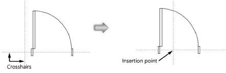
When editing components, make the object edits in the Attributes and/or Object Info palette. To edit the symbol insertion point, select all the components of the symbol, and relocate the components about the insertion point (origin) crosshairs. The intersection of the crosshairs gives the feedback segment Locus when encountered.
The other component of a hybrid symbol is not automatically adjusted to match changes made to the insertion point. It must be edited separately. Switch easily to the other component from the context menu.
A master snap point can be created when editing a symbol definition, setting the location by adding a 2D and/or 3D locus where priority snapping should occur, when enabled in the Snap to Object tool (see Snapping to an object). Place the locus with the appropriate component (2D locus for 2D component, 3D locus for 3D component). In the Object Info palette of the selected locus, select Master Snap Point. If the master snap point is in an obscure location and you want it to always display when the snap box is over the symbol instance, select Show Master Snap Point Outside Snap Box.
After editing, exit object editing mode to modify the symbol definition. The instances of black and green symbols are also updated.
If the edited symbol is nested within another symbol, the Exit Symbol button takes you up a level to the symbol container.
